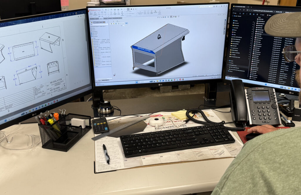
Design for manufacturing DFM is the discipline of refining part shapes, hole spacing, bend radii, and material specs during the CAD stage, so components advance through the manufacturing process without costly rework. We also catch manufacturing issues at the design phase, since fixing them later increases machining time and material waste considerably.
Our experienced fabrication team operates in Red Oak, Iowa, and our DFM review analyzes your 2D and 3D CAD files, including .STEP, .SLDPRT, and .DXF formats. We then adapt your design to our machinery, which include a 20 kW fiber laser, 350-ton Bystronic press brakes, a 3D tube laser, and our powder coating line. This work helps mid-sized OEMs reduce part costs, improve structural integrity, stabilize the supply chain, and shorten lead times.
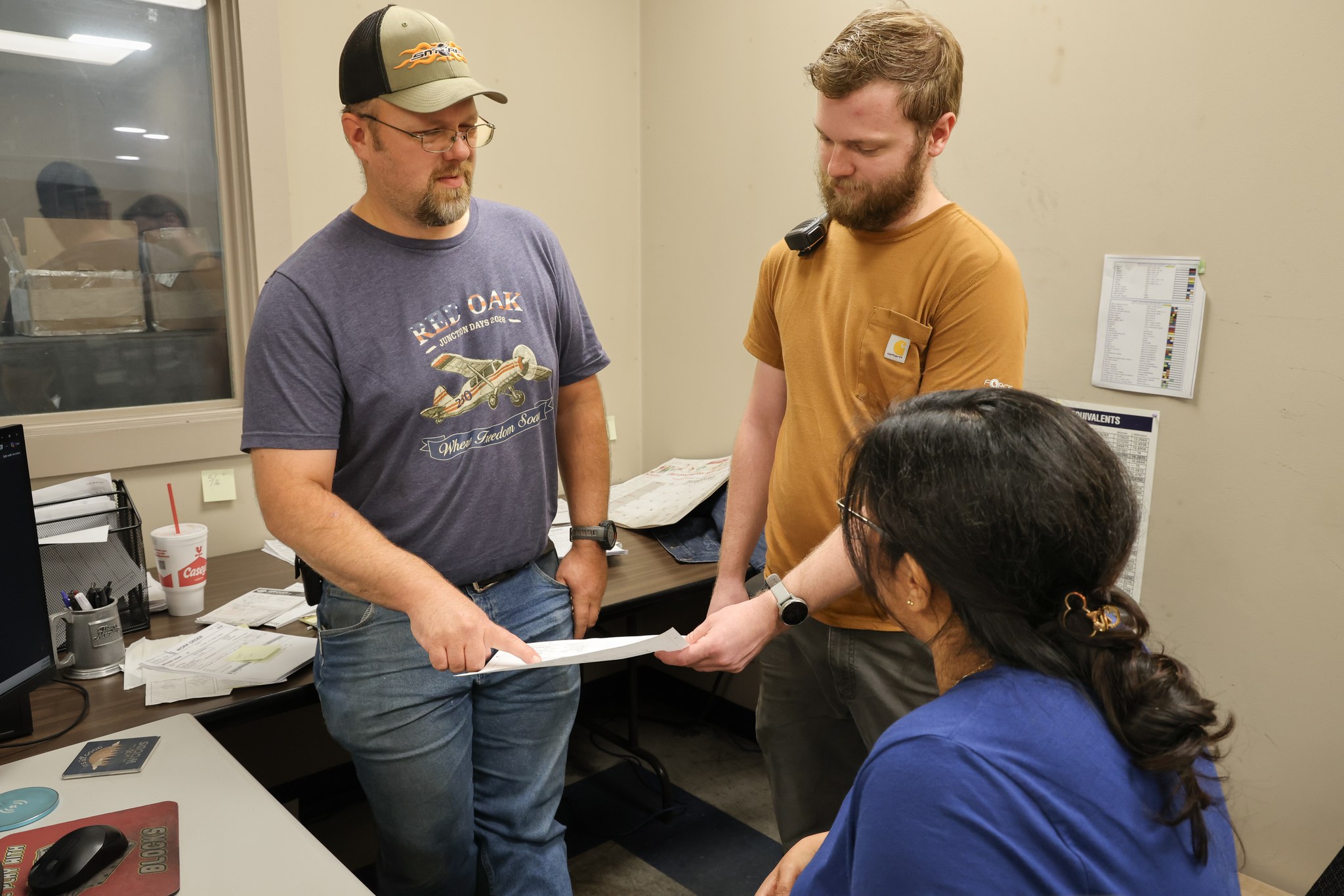
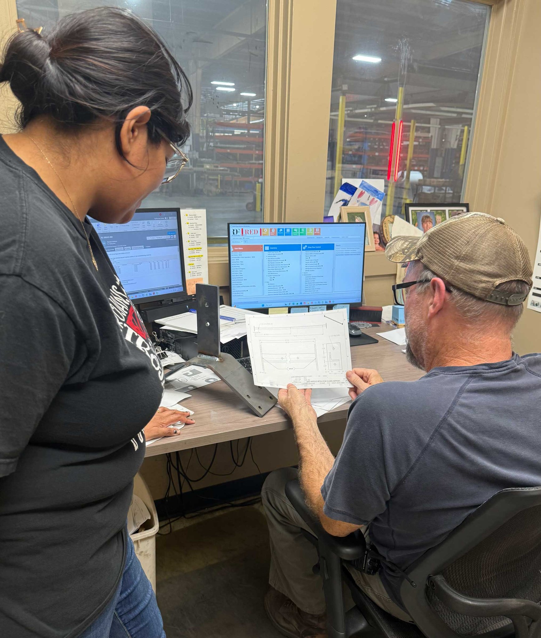
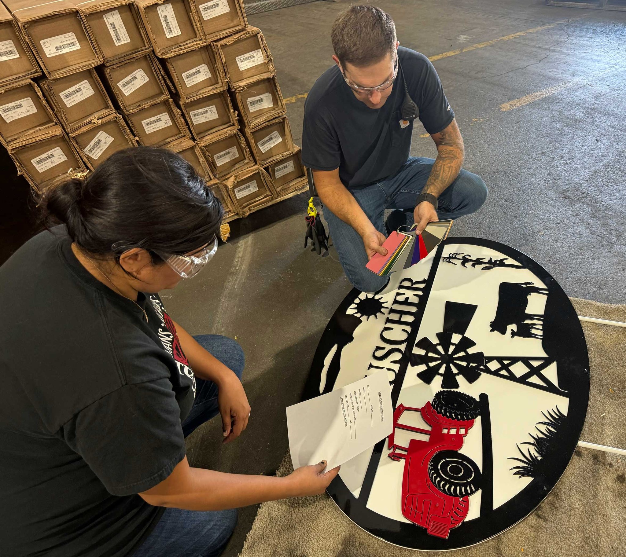
Design for manufacturing DFM is Red Oak Fabrication’s review process, and it aligns your CAD part designs with realistic, real-world manufacturing technologies. We fine-tune sheet metal gauges, bend radii, hole-to-edge spacing, weld tabs, and drain holes, so we eliminate production bottlenecks in fiber laser cutting, press brake forming, AWS certified welding, and powder coating.
Tight dimensional tolerances can affect manufacturability, so our team evaluates each critical feature to keep every design cost effective before production begins.
Your material choice influences raw stock costs, efficient manufacturing, lead times, and the wider supply chain.
Non-standard thickness increases cost and lead times, so we guide OEMs toward standard Midwest stock gauges in ASTM A36 carbon steel, 304 or 316 stainless steel, and 6061 or 5052 aluminum.
Components that fit efficiently on large sheets waste less material, and our Cutlite Penta fiber laser bed runs 13.3 by 6.7 feet, so efficient layout minimizes scrap and lowers each part cost.
On heavy plate jobs, orient key bend lines perpendicular to the metal grain, which helps prevent edge cracking during high-tonnage press brake forming.
Improper bend rules generate flange distortion, tooling collisions, and cracking, and these defects increase machining time and total fabrication cost.
A consistent radius lets our operators form components with a single press brake setup, which reduces custom tooling requirements and setup costs.
A bend near an edge or notch can tear the material, so a simple relief slot, as wide as the material is thick, stops that tearing.
Each bend flange must be tall enough to bridge the lower V-die on our 350-ton Bystronic press brakes.
High-speed laser cutting enables intricate hole patterns yet features positioned too close to edges or bends may distort during forming, and these are common manufacturing issues we flag early.
Position holes and slots at least two times the material thickness away from any bend line, and this stops holes from stretching during the bend.
For clean piercing on thick plate, make hole diameter equal to or larger than the plate, so in half-inch steel you use a half-inch minimum hole.
Maintain proper mounting hole tolerances and edge distances for automated PEM nut, stud, and standoff installation.
Designing for downstream welding and coating eliminates hours of manual shop labor, and it also conserves machining time and keeps the manufacturing process efficient.
Our 3D tube laser and 2D fiber lasers cut mating tabs and slots, so components snap together in precise alignment, which eliminates costly welding fixtures and reduces fit-up time.
For heavy structural weldments, we design direct 45-degree bevels on our 3D tube laser, and this ensures full joint penetration with no manual grinding.
Parts entering our powder line require small drain and hanging holes, so pretreatment chemicals drain completely and parts hang cleanly with no surface shadows.
Upload your 3D models or 2D vector files during the quoting phase so our team can start work.
Our drafting team checks part features against real machine limits, such as laser wattages, press brake tooling, and robotic weld clearances.
We provide recommendations to simplify geometries, reduce drop scrap, minimize custom tooling, and eliminate secondary operations that raise cost.
We work from four specialized facilities in Red Oak, Iowa to provide comprehensive single-source metal fabrication. Learn more about all of our turnkey capabilities.
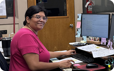
Jim leads both our drafting and laser teams so he knows the importance of having a perfect CAD file. If a small change to a bend, a hole or a flange happens, his team will tell you while the design can still move.

We reply in 1 business day. We deliver turnkey in 4–6 weeks from PO. Send us your print — we’ll take it from there.
We reply in 1 day & deliver turnkey in 4–6 weeks from PO.
